 in the icare toolbar (fundamental TE10 mode) :
Rectangular Horn : Waveguide Source
For this case, the geometry is the same geometry as for the previous case. For comparison, it is very convenient to open the previous case and to save it with another name. This keep the same geometry and the same electromagnetic data, including the requested outputs.
Erase the second part of the waveguide which contains the wire.
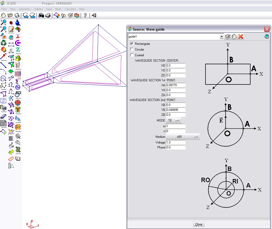
To define the waveguide source use  in the icare toolbar (fundamental TE10 mode) :
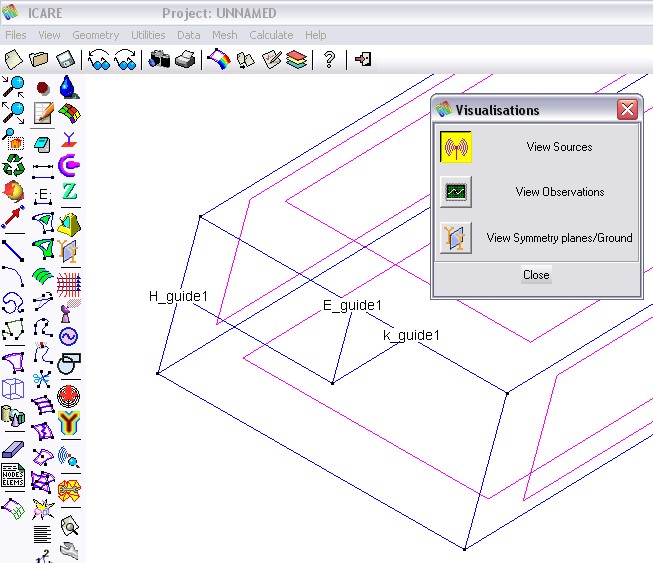
Check the source orientation with the source visualization menu :
Save, generate mesh and run
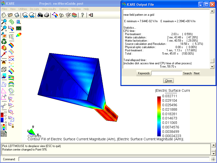
Computed surface currents, with a display of the CPU time :
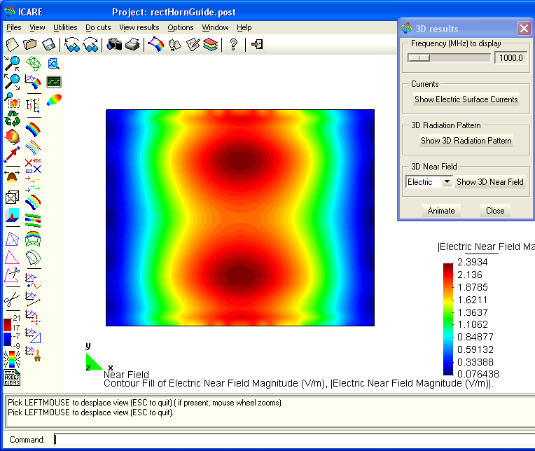
A view of the electric near field in the aperture of the horn :
Radiation patterns in the two main planes (phi=0° and phi=90°) :
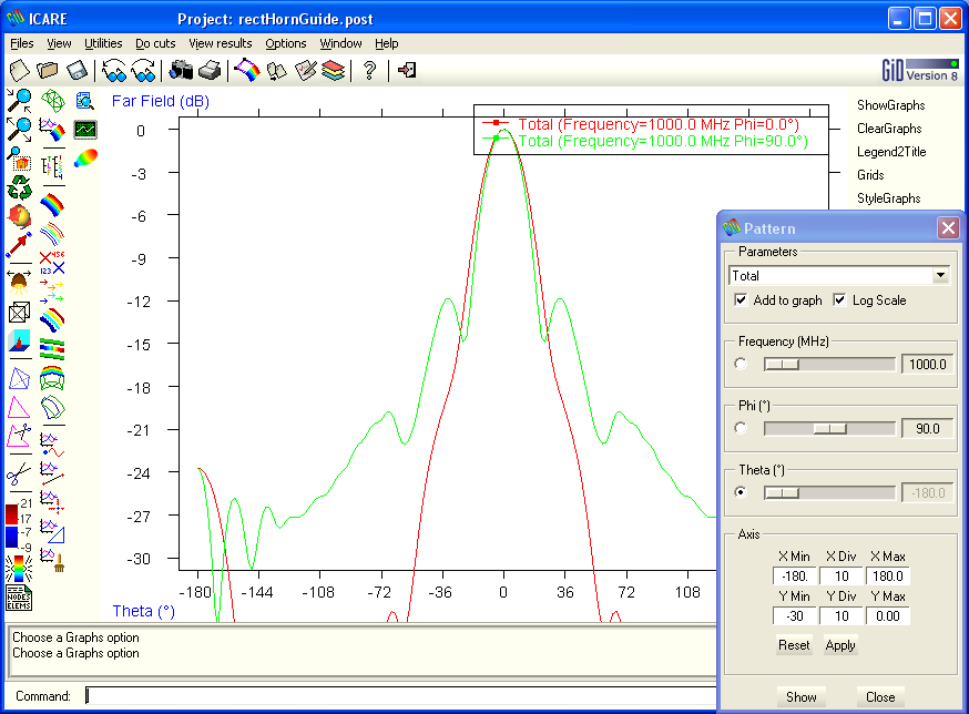
The computation time is slightly lower since the wave guide is smaller. In addition, there is a factor between the surface currents results. The same factor exists for the near field. This is due to a different definition of the voltage on a wire and in a waveguide. Since the far field is normalized, the effect of this factor disappears.
Copyright © 2015, IEEA