Open Gid and choose Problem Type Icare as explained in section Set Up
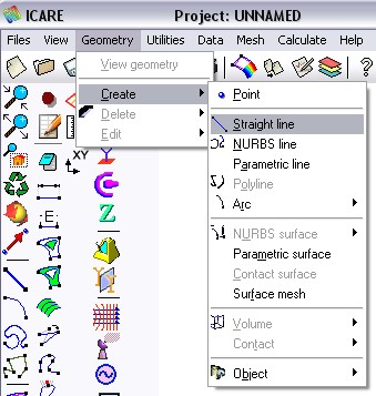
Create a line :

or with  in the left toolbar.
Enter the coordinates of the line's extremities in command line of Gid (at the bottom of the wndow) or click on the gid main window to set them.
First point : 0 0 0
Second : 0 0 0.25
Third : 0 0 0.5
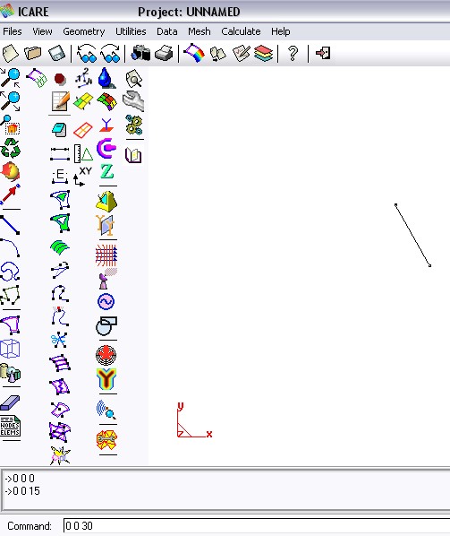
To cancel the line creation mode, press 'Esc' key or the middle-button of the mouse
To zoom on the wire click on 
The geometry being defined, the electromagnetic parameters shall be initialized.
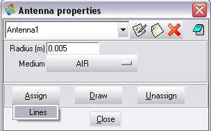
The wire represents the antenna. A property has to be added to define the radius.
Click on  to open the antenna window.
The radius default parameter is 5 mm.
Click on "Assign" then "Lines" :
Select the lines with the mouse.
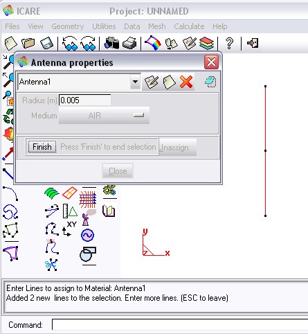
Press 'Esc' or middle-button or click on 'Finish'
and 'Close'
Click on  to set the the voltage source.
Name the source(optional) and assign it to the middle point
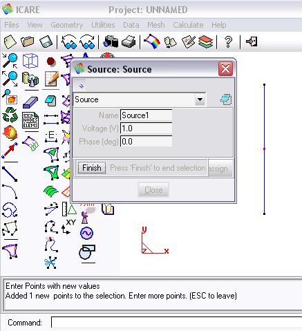
All required properties have been defined.
Enter the operating frequency using 
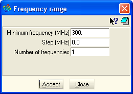
To define the far field pattern click on 
Select Pattern on the top of the far field calculation window :
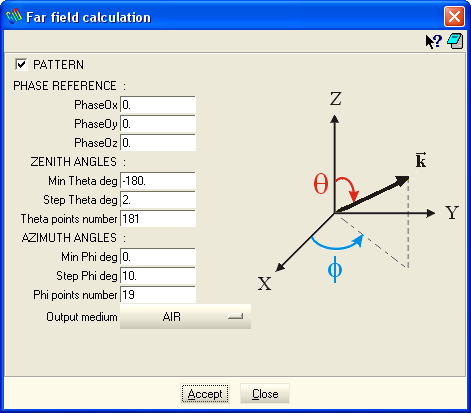
The source and the pattern can be visualized using 
Source visualisation:
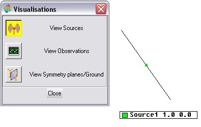
Far field visualisation :
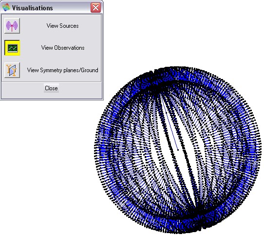
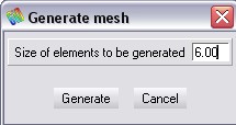
The option window  allows choosing the number of elements per wavelength which defines the mesh accuracy. The default value is λ/10.
Click on  to build the mesh
Save your project with 
Run Icare with 
Once the calculation is finished, the results may be visualized by selecting Post-Process
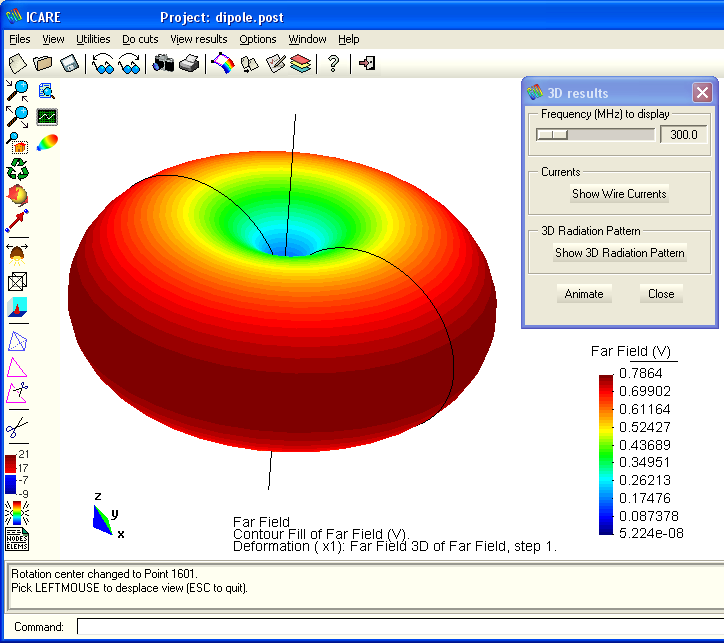
To view the 3D far field pattern, use the  button and click on the "Show 3D radiation Pattern" button :
Clicking on  allows seeing the results file and find one particular result in this file.
To see the result for the input impedance value (classical result), select the keyword in the predefined list :
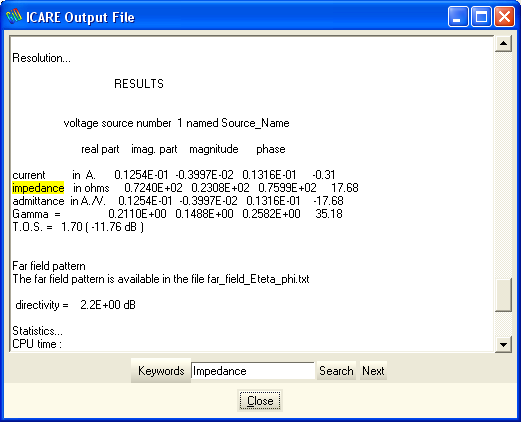
Congratulations for your first antenna simulation with ICARE !
Copyright © 2015, IEEA